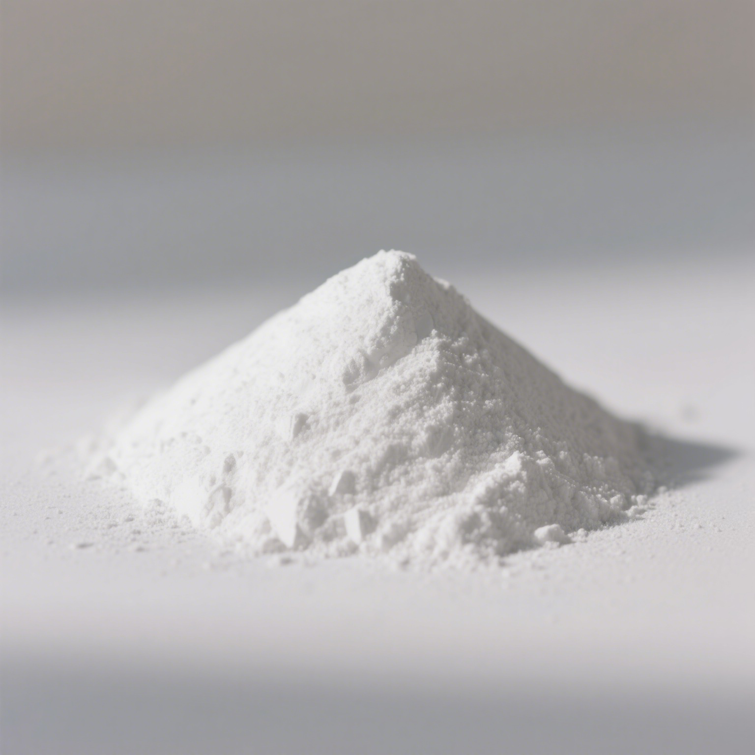
High-performance electronics, 5G infrastructure, and electric vehicle battery systems hit hard thermal bottlenecks. As power densities scale up, these systems require Thermal Interface Materials (TIMs) that dissipate massive heat loads without destroying manufacturing processability. Pushing standard filler volumes to hit thermal conductivity targets above 5 W/m·K spikes polymer matrix viscosity. This viscosity surge causes automated dispensing failures, poor surface wet-out, and accelerated wear on mixing equipment. The compound simply becomes too thick to process on high-speed assembly lines.
Specifying the right spherical alumina for thermal interface materials balances thermal transfer with rheological stability. The spherical morphology maximizes packing density while keeping the compound fluid and pumpable. We will break down the technical evaluation criteria, particle distribution strategies, and implementation risks you must assess when sourcing this filler for advanced thermal management.
Morphology Dictates Processability: The highly uniform spherical shape of the alumina reduces surface area and friction, enabling high filler loading (up to 90wt%) while maintaining the low viscosity required for automated dispensing.
Particle Size Distribution (PSD) is Critical: Achieving optimal packing density requires precise, multi-modal blending of spherical alumina particle sizes to fill interstitial voids without agglomeration.
Purity Impacts Reliability: High alpha-phase content ensures maximum thermal conductivity, while strict control of ionic impurities (Na+, Cl-) is non-negotiable for preventing electrical shorts in sensitive electronic packaging.
Surface Treatment Drives Compatibility: Untreated alumina often suffers from poor matrix compatibility; silane or titanate coupling agents are necessary to reduce interfacial thermal resistance and improve dispersion.
Performance Baselines: Why Spherical Alumina Powder Dominates TIM Formulations
Thermal interface material formulators operate under strict physical constraints. They need a thermal conductive filler that delivers bulk conductivity between 3 and 8+ W/m·K while ensuring the final compound remains highly pumpable or compressible. Hitting this target requires abandoning traditional, irregularly shaped filler particles. The physical shape of the filler directly controls how the material behaves under shear stress during compounding and application.
The rheological differences between spherical and angular alumina dictate production viability. Angular particles feature sharp edges and irregular surfaces. When mixed into a silicone or epoxy matrix, these angular particles physically interlock. As filler loading increases to achieve higher thermal conductivity, this interlocking creates massive internal friction. The material exhibits shear-thickening behavior, meaning viscosity spikes exactly when you try to pump it. The resulting compound turns into a stiff, unworkable paste long before it reaches the target thermal conductivity.
In contrast, spherical alumina powder acts on a microscopic level like ball bearings. The smooth, rounded surfaces slide past one another easily. This superior material mobility reduces shear stress during compounding and allows the material to flow smoothly through automated dispensing nozzles, even at extreme loading levels approaching 90% by weight. The compound maintains a pseudoplastic or Newtonian flow profile, ensuring consistent dispensing rates on the assembly line.
Beyond flowability, morphology directly impacts equipment longevity. Manufacturing TIMs involves high-shear planetary mixers, three-roll mills, and precision dispensing nozzles. Angular alumina is highly abrasive. It acts like liquid sandpaper against metal stators and rotors. This abrasion leads to frequent equipment breakdowns, nozzle clogs, and costly production downtime. The spherical morphology significantly reduces this abrasiveness. By minimizing the wear and tear on mixing and dispensing infrastructure, manufacturers keep continuous production lines running and lower their maintenance burdens. Progressive cavity pumps and static mixers operate efficiently over millions of dispensing cycles when processing spherical fillers.
Thermal conductivity relies on the efficient transfer of phonons through the material matrix. Every time a phonon encounters a gap or a polymer interface, thermal resistance increases. By utilizing spherical particles, formulators pack more thermally conductive material into the same volume, creating wider, more continuous pathways for heat transfer. The spherical shape minimizes the surface-area-to-volume ratio, meaning less polymer resin is required to wet the surface of the particles. This leaves more free resin available to lubricate the bulk material, balancing thermal performance with manufacturing processability.
Rheological and Mechanical Impact: Spherical vs. Angular Alumina
Filler Type
Maximum Loading (wt%)
Viscosity Profile at High Shear
Equipment Wear Rate
Dispensing Suitability
Angular Alumina
65% - 70%
Shear-thickening (Dilatant)
High (Abrasive)
Poor (Prone to clogging)
Spherical Alumina
85% - 90%
Shear-thinning (Pseudoplastic)
Low (Smooth surface)
Excellent (High flow rate)
Evaluation Dimensions: Spherical Alumina Particle Size and Packing Density
Achieving the theoretical maximum packing fraction is a complex physics challenge based on particle packing models like Andreasen or Dinger-Funk. If a formulator uses only a single size of spherical particles, large interstitial voids will inevitably remain between the spheres. In a polymer matrix, these voids fill with the base resin, typically silicone, epoxy, or polyurethane. Because polymers are thermal insulators, excessive resin pooling between particles severely bottlenecks heat transfer. To maximize thermal pathways, formulators must fill these voids with progressively smaller particles, driving up the density of the high loading spherical alumina network.
Multi-modal blending strategies are essential for optimizing this packing density. A carefully engineered formulation typically relies on three distinct particle size fractions to eliminate insulating resin pockets.
Establish the Primary Network: Introduce coarse fractions (e.g., 40-70 µm). These large spheres form the primary thermal conductive network. They act as the main highways for phonon transport across the bond line.
Fill Primary Voids: Blend in medium fractions (e.g., 10-20 µm). These particles are sized specifically to fit into the primary interstitial spaces created by the coarse fraction, displacing insulating polymer resin.
Maximize Bulk Density: Add fine fractions (e.g., 1-5 µm). The smallest particles fill the secondary and tertiary voids. This final layer of packing maximizes the bulk density and pushes the thermal conductivity to its absolute limit.
Selecting the right spherical alumina particle size distribution is only part of the evaluation. You must also scrutinize uniformity and batch consistency. Average particle size (D50) is a useful metric, but the strict uniformity of the entire distribution curve (D10 to D90) across multiple production batches guarantees predictable rheology. If a supplier's manufacturing process allows the fine fraction to drift, or if agglomerates form during shipping, the viscosity of the final TIM will fluctuate wildly. Consistent particle size distribution ensures that mass production runs yield identical flow rates and thermal impedance values every time.
Formulators must carefully navigate rheological trade-offs when designing these multi-modal blends. There is a delicate balance between maximizing packing density and maintaining a workable material. Over-indexing on ultrafine particles (sub-micron to 2 µm) dramatically increases the specific surface area of the filler blend. A higher surface area acts like a sponge, absorbing the liquid polymer resin. When the resin is locked onto the surface of millions of tiny particles, the bulk material loses its mobility, resulting in a sudden and severe spike in viscosity. Engineering the ideal blend requires just enough fine particles to fill the voids without starving the system of the free resin needed for lubrication and flow.
Material Purity, Phase Composition, and Surface Chemistry
The intrinsic thermal conductivity of an alumina particle depends entirely on its crystalline structure. You must rigorously verify the alpha-phase conversion rates of the powder. High-quality spherical alumina undergoes high-temperature calcination or plasma processing to ensure an alpha-alumina content typically exceeding 95%. The alpha phase is the most thermodynamically stable and dense crystalline form of aluminum oxide, offering an intrinsic thermal conductivity of roughly 30 W/m·K. Lower conversion rates indicate the presence of transitional phases, such as gamma or theta alumina. These transitional phases have disordered crystalline structures that scatter phonons, drastically reducing the intrinsic thermal conductivity of the particle and degrading the performance of the final TIM.
Beyond phase composition, strict control over ionic impurity thresholds is a non-negotiable requirement. Trace elements like sodium (Na+), chloride (Cl-), iron (Fe), and silicon (Si) frequently contaminate lower-grade alumina deposits. In high-power applications, these impurities pose a severe reliability risk. When subjected to high heat and humidity, common in automotive and telecommunications environments, mobile ions migrate through the polymer matrix. This migration leads to current leakage, dielectric breakdown, or the corrosion of delicate copper traces. For sensitive applications, demand certificates of analysis proving that ionic impurities are held to single-digit parts-per-million (ppm) levels, verified via ICP-OES testing.
Even with perfect morphology and high purity, untreated alumina struggles to integrate smoothly into organic polymer matrices. Aluminum oxide is naturally hydrophilic, while silicones and epoxies are hydrophobic. This chemical mismatch causes the filler particles to agglomerate rather than disperse evenly. To resolve this, surface modification is required. Applying a low viscosity alumina filler treatment, typically using silane or titanate coupling agents, fundamentally alters the surface chemistry of the particle.
Surface treatments serve multiple functions in a TIM formulation. First, they reduce the surface energy of the alumina, making it highly compatible with the surrounding resin. This compatibility prevents filler settling during storage and dramatically lowers the viscosity of the uncured compound. Second, the coupling agent creates a chemical bridge between the inorganic ceramic particle and the organic polymer network. This tight bond improves the wetting of the particle by the resin, displacing microscopic air pockets. By eliminating these air gaps, the surface treatment significantly reduces interfacial thermal resistance, allowing heat to flow seamlessly from the polymer into the conductive filler network.
Formulating Spherical Alumina for Electronic Packaging and Mobility
The application landscape for thermal interface materials dictates the specific formulation strategy. Different end-use environments require distinct combinations of viscosity, structural integrity, and thermal conductivity. Understanding these solution categories helps you specify the exact grade of spherical alumina for electronic packaging and automotive mobility required for your production lines.
Thermal gap fillers are liquid-dispensed materials designed to bridge varying gaps between heat-generating components and heat sinks. These formulations require highly spherical, tightly controlled multi-modal blends to ensure high flow rates. During assembly, the gap filler must compress easily under minimal pressure to avoid placing mechanical stress on delicate flip-chip packages or fragile solder joints. The spherical morphology ensures the material spreads evenly, filling microscopic surface irregularities without requiring excessive clamping force.
In the electric vehicle sector, mobility and battery thermal management present unique challenges. Battery packs generate significant heat during rapid charging and discharging cycles. Formulators use spherical alumina in potting resins and structural adhesives that encapsulate cylindrical or prismatic battery cells. The material must flow effortlessly around complex geometries and deep crevices within the battery module. Once cured, the heavily loaded potting compound regulates temperatures across the entire pack, dissipating heat away from individual cells to prevent localized hotspots and mitigate the risk of thermal runaway.
Thermal pads and thermal greases represent the two extremes of the viscosity spectrum, yet both rely heavily on spherical alumina to function correctly in the field.
Thermal Pads and Greases Application Summary
Application Type
Viscosity Requirement
Loading Density
Primary Function
Thermal Pads
High (Pre-cured solid)
Very High (Up to 90wt%)
Provides structural integrity, vertical thermal conductivity, and shock absorption between components and chassis.
Thermal Greases
Low to Medium (Paste)
High (Ultra-fine blends)
Achieves minimal bond line thickness (BLT) to eliminate microscopic air gaps on CPU/GPU IHS surfaces.
Potting Compounds
Low (Liquid pourable)
Medium to High
Encapsulates battery cells, providing environmental protection and bulk heat dissipation.
Liquid Gap Fillers
Medium (Thixotropic)
High
Dispenses vertically without slumping, curing in place to bridge variable tolerances.
Thermal pads tolerate slightly higher viscosities during manufacturing because they are calendered and pre-cured into solid sheets. However, they still require extremely high filler loading to achieve the necessary vertical thermal conductivity while remaining soft enough to conform to surface warpage. Thermal greases, conversely, depend on ultra-fine spherical alumina blends. Greases must achieve the thinnest possible bond line thickness (BLT) to minimize thermal resistance. The spherical particles allow the grease to spread into a microscopic layer under mounting pressure, while resisting the pump-out degradation that occurs when thermal cycling forces inferior greases out of the interface over time.
Implementation Risks and Sourcing Trade-offs
Procuring advanced thermal fillers requires navigating a complex matrix of performance and supply chain reliability. While spherical alumina is the dominant choice, engineering teams often evaluate alternative ceramic fillers. Aluminum Nitride (AlN) and Boron Nitride (BN) offer higher intrinsic thermal conductivity than alumina. However, they come with severe implementation risks. Aluminum Nitride is highly susceptible to hydrolysis. When exposed to ambient moisture, it reacts to form aluminum hydroxide and ammonia gas. This outgassing causes swelling, voids, and catastrophic failure in sealed electronic packages. Boron Nitride is highly anisotropic, meaning it conducts heat well in only one direction, making it difficult to align properly in liquid-dispensed TIMs. Spherical alumina provides a superior performance ratio, is electrically insulating, and remains completely stable in high-humidity environments.
Supply chain and sourcing risks are major factors for procurement teams. Manufacturing high-quality spherical alumina requires highly specialized equipment. The two primary methods are high-temperature flame fusion and plasma synthesis. Flame fusion is more common, producing excellent sphericity for most commercial applications. Plasma synthesis operates at much higher temperatures, yielding near-perfect sphericity, tighter uniformity, and fewer agglomerates. You must evaluate the global manufacturing landscape. Heavy reliance on single-region sourcing exposes production lines to geopolitical risks, shipping delays, and tariff fluctuations. Establishing localized or diversified supply chains ensures uninterrupted production during global disruptions.
To mitigate implementation risks, manufacturers must establish rigorous incoming Quality Control (QC) protocols. Relying solely on supplier datasheets is a fast track to batch failures when formulating high-performance TIMs. Implement strict verification steps before allowing raw powder into full-scale compounding.
Laser Diffraction Testing: Verify the Particle Size Distribution (PSD) upon receipt. Confirm that the D10, D50, and D90 metrics align precisely with the agreed-upon specification to prevent unexpected viscosity spikes.
Scanning Electron Microscopy (SEM): Conduct periodic SEM imaging to verify sphericity and check for the presence of fused particles or broken angular shards that could damage dispensing equipment.
Rheometer Baselines: Perform small-batch lab mixing and rheometer testing to establish viscosity and shear-thinning baselines in the specific polymer matrix before committing to a full production run.
Dielectric Withstand Testing: For electronic packaging applications, verify the breakdown voltage of the cured compound to ensure ionic impurities are within safe operational limits.
ICP-OES Impurity Screening: Run inductively coupled plasma optical emission spectroscopy to confirm sodium and chloride levels remain below the specified ppm thresholds.
Conclusion
Request sample lots of multi-modal blends tailored to your specific target bond line thickness and dispensing equipment.
Conduct rheological and thermal impedance testing using your proprietary silicone or epoxy matrix to verify flow rates and thermal transfer.
Validate dispensing equipment compatibility by running accelerated wear tests on stators, rotors, and nozzles.
Audit supplier quality control processes to ensure batch-to-batch consistency for critical PSD and ionic impurity metrics.
FAQ
Q: What is the ideal spherical alumina particle size for thermal gap fillers?
A: The ideal size relies on multi-modal blends rather than a single dimension. Formulators typically utilize a primary coarse particle size of 40-70 µm mixed with medium 10 µm and fine 2 µm fractions. This specific blending strategy optimizes packing density, allowing for high thermal conductivity while maintaining the flowability required for liquid dispensing.
Q: How does high loading spherical alumina affect the viscosity of silicone TIMs?
A: While high filler loading naturally increases viscosity, the spherical shape mitigates this spike significantly compared to angular fillers. The smooth, rounded surfaces act like ball bearings, reducing internal friction. This allows formulators to achieve up to 85-90 wt% loading while maintaining a low viscosity profile suitable for automated pumping.
Q: Why is spherical alumina preferred over aluminum nitride for electronic packaging?
A: Although Aluminum Nitride (AlN) offers higher intrinsic thermal conductivity, spherical alumina is electrically insulating and highly stable. Crucially, alumina is not susceptible to hydrolysis. AlN reacts with moisture in humid environments to produce ammonia gas, which causes catastrophic swelling and failure in sealed electronic packages.
Q: How is spherical alumina powder used in EV mobility applications?
A: It is a critical component in thermal gap fillers and potting compounds used for battery packs. The powder provides the necessary thermal conductivity to dissipate heat away from battery cells. Its flowability ensures the material navigates complex geometries during automated dispensing, regulating temperatures without damaging sensitive cells.
Q: What is the difference between flame fusion and plasma-synthesized spherical alumina powder?
A: Flame fusion uses high-temperature gas flames to melt and shape the alumina, offering a reliable solution for most applications. Plasma synthesis utilizes ultra-high-temperature plasma arcs, which yields higher sphericity, tighter size uniformity, higher alpha-phase purity, and fewer agglomerates.
Q: How do surface treatments on thermal conductive fillers improve TIM performance?
A: Surface treatments, such as silane or titanate coatings, reduce the surface energy of the alumina particles. This improves their dispersion within the hydrophobic polymer matrix, lowers the overall viscosity of the uncured compound, and reduces interfacial thermal resistance by eliminating microscopic air gaps between the particle and the resin.